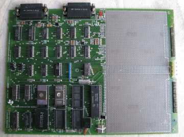
 Description
 Power Supply
 Jumper Positions
 EPROMs and PROMs
 Memory Map
 CRU Address Map
 LED
LED Connecting to a PC
 Powering On and Detecting the Baud Rate
 EVMBUG System Monitor
TMS 9995 Evaluation Module
 Description
 Power Supply
 Jumper Positions
 EPROMs and PROMs
 Memory Map
 CRU Address Map
 LED
LED
 Connecting to a PC
 Powering On and Detecting the Baud Rate
 EVMBUG System Monitor
 |
Quote from this marketing brochure: "The TMS 9995 evaluation module (TMAM 6095) is a stand alone microcomputer board that supports evaluation of TMS 9995 software and hardware features as well as prototyping of TMS 9995 interfaces. This module contains a powerful monitor that enables programs to be assembled, edited, and executed. The powerful symbolic assembler also provides reverse assembly capability. Hardware features include two EIA data communication links that provide for interface to a local terminal and to a host system for up-load/down-load capability. In addition to the 256 bytes of on-chip RAM provided by the TMS 9995, 1K bytes of external RAM is populated. Six kilobytes of EPROM is populated containing the monitor and assembler; however, up to 24K of EPROM may be used by populating the three 28-pin sockets with TMS 2564 EPROMs. Personality modules for each of the three 28-pin sockets may be configured to allow use of virtually any X8 organised memory. A large prototyping area provides ample room for breadboarding of TMS 9995 systems." Some information on the module is also available on this page from the TI Microsystems Designers Handbook. (The TMAM 9000 series development system mentioned is TI's disk-based Advanced Microprocessor Prototyping Laboratory (AMPL) system.) This web page describes the module in its 'standard' configuration as supplied new. Take all information with a pinch of salt - it is derived by disassembling the code in the EPROM and by examination of the physical board itself, and may contain some errors. A scan of the manual for this module has become available here. |
The module requires +12V, -12V and +5V supplies, as marked on the board.
Actually, the +/-12V supplies are only used by the RS-232 ports, and as the RS-232 specification only calls for a minimum of +/-3V logic levels, the module works with the +/-12V supplies connected to +/-5V supplies, if that is more convenient. (This is certainly the case with the -12V supply, I haven't actually tried running the +12V at +5V.) I've powered the module using the internal power supply removed from a spare TI-99/4A computer.
Note that the red LED is not a power on indicator - its function is described here.
J1 - set to position 1-2 if EPROM at position U8 is a 2516, or position 2-3 if EPROM is a 2532.
J2 - ditto J1 for EPROM at position U9.
J3 - ditto J1 for EPROM at position U10.
(Jumpers J1/J2/J3, in conjunction with the EPROM personality modules, determine the signal routed to the EPROM pin 20. With a 2516 EPROM, pin 20 is /CS, and with a 2532 EPROM, PD/PGM.)
J4 - set to position 1-2 if the EPROM at position U8 does not require
a wait state, or position 2-3 if it does.
J5 - ditto J4 for EPROM at position U9.
J6 - ditto J4 for EPROM at position U10.
J7 - position 2-3 enables the Automatic First Wait State (AFWS) generation feature of the processor for slow memories. Position 1-2 disables the feature.
J8 - set to position 1-2 if a TTY terminal is connected to port P1, or position 2-3 if an RS-232 terminal is connected to the port.
The monitor software is programmed in two EPROMs:
A hex dump of the EPROMs along with partially disassembled source code is available here. For the source code that is not yet disassembled, some of it is the same as or similar to the TIBUG monitor.
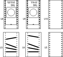
A socket for an EPROM 'personality module' (a DIL header plug) is located adjacent to each EPROM socket. The personality modules route the memory bus control signals to the correct pins of the EPROMs, which vary according to EPROM type. The wiring of each module is shown below. The personality module for the TMS 2532 EPROM may have a lid glued on and be printed with the part number 1603153-2. Thanks Philip for the wiring info.

Two bipolar PROMs provide address decoding:
| >FFFF | TMS 9995 On-chip RAM | (4 bytes) |
| >FFFC | ||
| >FFFB | TMS 9995 On-chip Decrementer | (2 bytes) |
| >FFFA | ||
| >F0FB | TMS 9995 On-chip RAM | (252 bytes) |
| >F000 | ||
| >EFFF | RAM | U6 and U7 - D2148 (1K bytes total) |
| >EC00 | ||
| >17FF | Monitor EPROM | U9 - TMS 2516 (2K bytes) |
| >1000 | ||
| >0FFF | Monitor EPROM |
U8 - TMS 2532 (4K bytes) |
| >0000 |
The monitor software has its workspace in RAM at >EC00 and also appears to use various memory locations up to >EC62 inclusive.
The re-entry address to the monitor is >0142. This displays the MON? prompt and waits for the next command.
Base address of port P1 TMS 9902: >0000
Base address of port P2 TMS 9902: >0400
The processor also has some internal CRU devices that are mapped into the CRU address space; refer to the TMS 9995 data manual.
Red LED CR2 is connected between the /IDLE signal on the scratchpad area of the module and +5V. Executing the IDLE command will make it light (IDLE suspends processor instruction execution until an unmasked interrupt level request occurs).
Port P1 is the RS-232 connector nearest the corner of the module, and the second RS-232 connector is port P2.
Connect port P1 to the PC using a standard RS-232 serial cable. (I've had the module running OK using a USB serial port device connected to the module with a standard 9-25 pin D-type adapter.)
Configure the serial port on the PC for 7 bits/character, even parity, 2 stop bits, no handshaking. The module will work with the following Baud rates: 110, 300, 600, 1200, 2400, 4800, 9600, 19200, so configure the port to one of these. After powering on or resetting the board, type 'A' (uppercase A) or <Return> and the module will autodetect the Baud rate and reply with the message "EVMBUG R1.0" followed by the command prompt "MON?".
The monitor program EVMBUG is based on TI's TIBUG monitor, which is used with the TM 990 range of microcomputer modules.
EVMBUG is described on this page.