TM 990 Series 16-bit Microcomputer Hardware Designs
This page covers my own TM 990 module hardware designs. These modules are for home/hobby use only. They are not designed or manufactured to any sort of commercial standard or specification.
Click here for the schematic diagram (opens in new window).
Click here for the PCB layout (opens in new window).
See the Assembly section below – the PCB layout shows the bottom of the PCB.
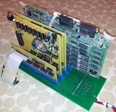
Note that all the components (connectors, resistors and LEDs) are fitted on the opposite side of the PCB to the yellow silk screen writing.
CAUTION! Take care removing the cable from the IDE connector on the V1 PCB. Due to a design oversight, the IDE connector is only soldered to the top of the board rather than being fitted through-hole. This problem is corrected on the V2 PCB.
Click here for the schematic diagram (opens in new window).
Click here for the PCB layout (opens in new window).
Address bus lines A0 (MS) – A14 (LS) and the /MEMEN (Memory Enable) input are buffered onto the board by octal bus transceivers U1 and U2. These transceivers are permanently enabled in one direction by the /G (Enable) input being tied low and the DIR (Direction) input being pulled high by resistor R1. The transceivers feature hysteresis on the inputs to improve noise immunity.
Memory mapped I/O address decoding is implemented as follows:
The inverted DBIN signal is combined with address bit A11 in OR gate U8a such that reads and writes to the IDE port have to take place at different memory mapped addresses. This is due to the processor’s read-before-write operation (before writing to a memory address, it first reads the data from that address in order to support byte-only instructions), which may confuse the IDE controller. Software must perform IDE read operations at addresses where A11 = 0 (for example at >8000), and perform IDE write operations where A11 = 1 (for example at >8010, where the OR gate prevents the read-before-write operation activating the IDE /READ signal). Cascaded OR gates U8b, U8c and U8d delay the /DBIN signal to give a falling edge on the IDE /READ signal after /CS0 becomes active.
Resistors R4, R5 and R6 help to prevent ringing on the IDE /WRITE, /READ and /CS0 lines.
LED D1 provides a 'drive active' indication, controlled by the IDE drive through the DASP signal.
The board operates from a single +5V power supply. Capacitor C1 provides power supply smoothing. The power supplies to individual ICs are decoupled by capacitors C2 – C9.
Notes
Some hard-wired modifications have been done on the V1 PCB to improve the design (these modifications are incorporated in the V2 PCB design). In the original design, the IDE /READ and /WRITE signals were derived from DBIN and /WE and were active during normal memory read and write cycles when the IDE drive was not selected. This worked fine for some IDE drives but for others, when reading the 256 words from the drive during a sector read, pulses on /WE when writing the words to the sector buffer in RAM would cause the read to fail. The board has therefore been modified to gate the IDE /READ and /WRITE signals with the IDE /CS0 signal - the drive then only sees activity on /READ and /WRITE when the drive is selected. This cures the problems with sector reads failing. The modifications are:
The board includes two sets of 8-way jumpers for setting the memory mapped I/O address. See the PCB layout diagram above for the position of these jumpers. One jumper is placed on one of the first set of jumper positions to select an 8K boundary chip select, and one jumper is placed on one of the second set of jumpers to select a 1K boundary chip select within the selected 8K boundary. The default jumper positions shown in the PCB layout diagram give a memory mapped I/O address space of >E000 - >E3FF.
The module is supported by simple disk operating system (DOS) software that normally resides at addresses >1000 - >1FFF. It is normally blown into EPROM on the TM 990/101 Processor module or stored in a read-only memory block on the battery-backed 64K Memory module. The software also uses memory addresses >F000 - >F67D for data storage and buffers.
The disk format used is a bespoke format and is not compatible with any PC disk formats. To access a disk on a PC, an application that reads/writes raw sectors is required, such as WinHex. It is recommended that such a program is obtained and used to regularly back up data on a TM 990 disk.
Note: WinHex normally requires the program to be 'run as administrator' to give access to the physical media rather than just a logical drive.
To run the software from TIBUG, enter the "D" command, or execute from memory address >1000. When run, the software displays a welcome message followed by a ">" command prompt.
The software supports the following commands, which are entered at the command prompt. In each case if the command requires further parameters, further prompts are displayed. Pressing <Esc> once or twice at any of the prompts aborts a command.
Displays the list of commands supported.
Clears the screen and redisplay the command prompt.
Displays the name/manufacturer of the drive (as stored in the drive’s firmware) and total number of sectors on the drive, followed by the disk name, numbers of sectors supported by the DOS and the number of sectors free.
Displays the current state of each bit of the drive status register.
Sends the 'spin down' command to the drive. This causes a mechanical HDD to spin down, but has no effect on a CF drive.
Sends the 'spin up' command to the drive. This causes a mechanical HDD to spin up, but has no effect on a CF drive.
Reading or writing to a drive that has been spun down automatically causes the drive to spin up.
Prompts for:
– sector number to display (in hex).
Displays the contents of the specified sector in hex data and ASCII character formats, then displays a prompt to display the next sector, the previous sector, or return to the command prompt.
Prompts for:
– start sector number (in hex);
– number of sectors to fill (in hex);
– word value to fill the sector(s) with (in hex).
Fills the specified sector(s) with the specified word value.
Prompts for:
– name for saved file (up 20 ASCII characters);
– memory address to start saving from (in hex);
– memory address to end saving at (inclusive, in hex);
– optional program execute address (in hex, defaults to start address if not specified);
– optional program description (up to 70 ASCII characters).
Saves the specified block of memory to disk.
If a file with the specified name already exists, prompts whether to overwrite the file.
If there is not enough space on the disk to store the file, displays an error message.
Prompts for:
– name of file to load (up 20 ASCII characters).
Loads the specified file into same memory block that it was saved from.
Prompts for:
– name of file to run (up 20 ASCII characters).
Loads the specified file into same memory block that it was saved from, then runs the program from the execute address specified when the file was saved.
Prompts for:
– name of file to rename (up 20 ASCII characters);
– new name for file (up to 20 ASCII characters).
Renames the specified file.
Prompts for:
– name of file to change the description of (up 20 ASCII characters);
– new optional program description (up to 70 ASCII characters).
Changes the (optional) program description for the specified file.
Prompts for:
– name of file to delete (up 20 ASCII characters).
Deletes the specified file.
Note: No delete confirmation prompt is displayed.
Prompts for:
– name for disk (up 20 ASCII characters).
Formats the disk.
Note: No format confirmation prompt is displayed.
Prompts for:
– new name for disk (up to 20 ASCII characters).
Renames the disk.
Lists the files on the disk, plus the number of sectors free.
For machine code programs and memory dumps, the command lists the program name, load address, execute address, end address, size and program description.
For BASIC programs and text files, the command lists the program name, size and program description.
Returns to the TIBUG command prompt.
The LOAD and SAVE commands can be accessed from within Cortex BASIC to load and save BASIC programs. The DIR and DELETE commands are also supported to assist with file management. To use these commands within Cortex BASIC, prefix each command with a "*" - that is, *LOAD, *SAVE, *DIR and *DELETE - then further prompts are displayed if required.
Note: In Cortex BASIC, all prompts and responses to these commands are sent over the serial terminal only. They will not be displayed on the VDP screen.
Click here for the schematic diagram (opens in new window).
Click here for the PCB layout (opens in new window).
Address bus lines A0 (MS) – A14 (LS) and the /MEMEN (Memory Enable) input are buffered onto the board by octal bus transceivers U1 and U2. These transceivers are permanently enabled in one direction by the /G (Enable) input being tied low and the DIR (Direction) input being pulled high by resistor R1. The transceivers feature hysteresis on the inputs to improve noise immunity.
4-to-16 line decoder U5 decodes high-order address bits A0 – A3 to split the processor 64K byte address space into blocks of 4K bytes. The decoder is enabled when /MEMEN is active during processor memory cycles.
The outputs from U5 are fed to two banks of selection circuits:
When a memory access takes place, if the switch for the corresponding memory bank is closed then the output from U12c is low. If the switch for the corresponding memory bank is open then the output from U12c remains high.
The output from U12c forms the RAM chip enable signal. It is fed to the /CE input of non-volatile controller U6 and the /G input of the data bus octal transceivers U3 and U4. The direction of U3 and U4 is controlled by the signal DBIN (Data Bus In), which is buffered onto the board and inverted by U9a. When DBIN is high, the direction of data transfer is off the board. When DBIN is low, the direction of data transfer is onto the board.
When a write memory access takes place, if the switch for the corresponding memory bank is closed then the output from U9f is low. If the switch for the corresponding memory bank is open or the memory access is a read operation then the output from U9f remains high.
The output from U9f forms the RAM write enable signal.
Non-volatile controller U6 monitors the +5V power rail for an out-of-tolerance condition. When such a condition is detected, the RAM /CE signal fed through the IC is inhibited to accomplish write protection and the RAM power output 5vB switches from the +5V power rail to the 3V battery input to supply the RAM with uninterrupted power.
RAM ICs U7 and U8 are both connected to the buffered address lines A0 – A14. U7 provides the high data byte and U8 the low data byte. The data bus is buffered on and off the board by octal transceivers U3 and U4 as previously described. /CS for both RAMs is supplied by the first selection circuit bank then through non-volatile controller U6. /WE is supplied by the second selection circuit bank. /OE is connected to the /DBIN signal from U9a such that the RAM outputs are enabled during memory read cycles.
The board operates from a single +5V power supply. Capacitor C1 provides power supply smoothing. The power supplies to individual ICs are decoupled by capacitors C2 – C11.
Notes
Connecting a 16 segment bar graph LED onto the output of the address decoder U5 gives a useful visual indication of which memory block(s) most memory accesses are taking place in.
By extending the circuit connections to enable/disable memory block 0 to an easily-accessible toggle switch, and doing the same for the EPROM enable jumper on the TM 990/101 Processor module, the system can be configured such that TIBUG can be loaded into RAM memory block >0000 and run from RAM rather than EPROM.
The board includes a pair of DIP switches to enable/disable each memory block and a pair of DIP switches to write protect each memory block. See the PCB layout diagram above for the position of these switches. The switch positions to maximise the amount of RAM available in the system are detailed in the following table (the individual switch numbers are indicated on the DIP switches themselves).
| Enable Memory Block Switches | Write Protect Memory Block Switches |
Switch Positions |
| SW2 switches 1, 2 | SW4 switches 1, 2 | Set these switches on SW2 to OFF to disable memory blocks >0000 and >1000 (the TM 990/101 Processor module maps EPROM (TIBUG and the IDE software) to the >0000 - >1FFF address range). These switches on SW4 can be set to either position as the memory blocks are disabled. |
| SW2 switches 3 - 8 | SW4 switches 3 - 8 | Set these switches on SW2 to ON to enable memory blocks >2000 - >7000, and set these switches on SW4 to ON to make these memory blocks read/write. |
| SW1 switches 1 – 6 | SW3 switches 1 - 6 | Set these switches on SW1 to ON to enable memory blocks >8000 - >D000, and set these switches on SW3 to ON to make these memory blocks read/write. |
| SW1 switches 7, 8 | SW3 switches 7, 8 | Set these switches on SW1 to OFF to disable memory blocks >E000 and >F000 (other hardware is memory-mapped to the >E000 - >EFFF address range and the TM 990/101 Processor module maps RAM to the >F000 - >FFFF address range). These switches on SW3 can be set to either position as the memory blocks are disabled. |
Jumper JP1 enables the battery supply to the non-volatile controller U6 to be easily disconnected to clear the RAM, if required.
Battery B1 is a 3V CR2032 type. It should be able to provide standby power to the RAM for several years.
Click here for the schematic diagram (opens in new window).
Click here for the PCB layout (opens in new window).
Address bus lines A0 (MS) – A14 (LS) and the /MEMEN (Memory Enable) input are buffered onto the board by octal bus transceivers U1 and U2. These transceivers are permanently enabled in one direction by the /G (Enable) input being tied low and the DIR (Direction) input being pulled high by resistor R1. The transceivers feature hysteresis on the inputs to improve noise immunity.
Memory mapped I/O address decoding is implemented as follows:
OR gates U8c and U8d and inverter U7f combine the chip select signal for the VDP with inverted address bit A13 and /DBIN to generate the read chip select signal for the VDP, /CSVR. OR gates U8a and U8b combine the chip select signal for the VDP with (non-inverted) address bit A13 and /WE to generate the write chip select signal for the VDP, /CSVW. The addresses at which these signals are active, and the VDP operations that they select, are shown in the table at the top right corner of sheet 1 of the schematic diagram.
The MOS 6581 SID sound chip U11 is addressed by address bits A10 – A14 and supplied with data through the high data byte D0 – D7. These address and data bits are latched by octal latches U10 and U9 whenever a write operation occurs to the SID memory mapped address space. The latch outputs are permanently enabled by their /OE input being tied low, and the SID is permanently enabled by its /CS input being tied low, so the SID continually processes the last data byte sent to it (programmers need to be aware of this and need to actively write a data byte to stop a note playing). Also note that SID is connected as an output device only (the R/W input is tied low) – it is not possible to read data from the SID. The SID is clocked at 1 MHz by oscillator OSC1.
The SID audio output is fed to volume control potentiometer R3, then via the DC blocking capacitor C12 to the audio output jack S1 and the audio amplifier formed by U13 and associated components. Jumper JP25 enables the on-board audio speaker to be silenced if the audio output jack is used.
The TMS 9918A VDP U100 is controlled through the chip select write (/CSVW), chip select read (/CSVR) and address bit A14. It is connected to the high data byte D0 – D7. The VDP is clocked at 10.738635 MHz by crystal X1. 16K byte of video RAM is provided by 16K x 1 bit RAMs U102 – U109. The VDP provides a composite video output which is fed to video output socket S2. The VDP video output requires an external pull-down resistor which is provided by potentiometer R6. This is typically set to 330 Ohms to provide a 1.9V synchronisation level. Jumper JP27 enables the VDP interrupt output to be optionally routed to the /INT2 line on the backplane and to the TM 990/101 Processor module.
The board requires three power supplies:
The board includes three sets of 8-way jumpers for setting the memory mapped I/O addresses for the VDP and SID. See the PCB layout diagram above for the position of these jumpers. One jumper is placed on one of the first set of jumper positions to select an 8K boundary chip select, and one jumper is placed on each of the second and third sets of jumpers to select a 1K boundary chip select within the selected 8K boundary for the VDP and SID. The default jumper positions shown in the PCB layout diagram give a memory mapped I/O address space of >E400 - >E7FF for the VDP and >E800 - >EBFF for the SID.
Adjust the audio volume potentiometer R3 to the required level (if necessary, contact me for some programs that play some audio through the SID). Fit jumper JP25 to play audio through the on-board amplifier and speaker.
Fit jumper JP27 if the VDP interrupts are to be routed to the TM 990/101 Processor module. (See this page for a tutorial on using VDP interrupts.)
Adjust the video level potentiometer R6 to give an acceptable video output. (Do not set the potentiometer below about 330 Ohms.)
