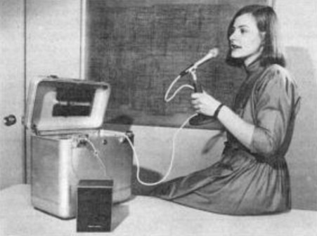
Earlier Portable Version (PASS) - "Suitcase with a memory for words"
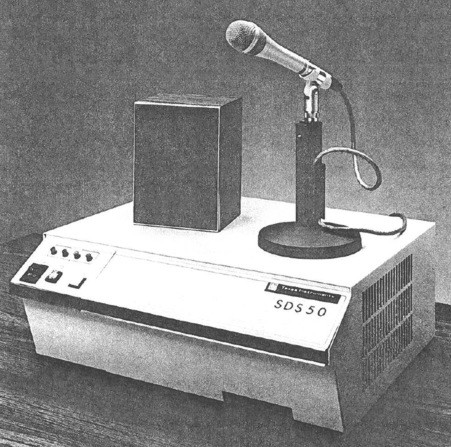
Later Desktop Version (SDS50)
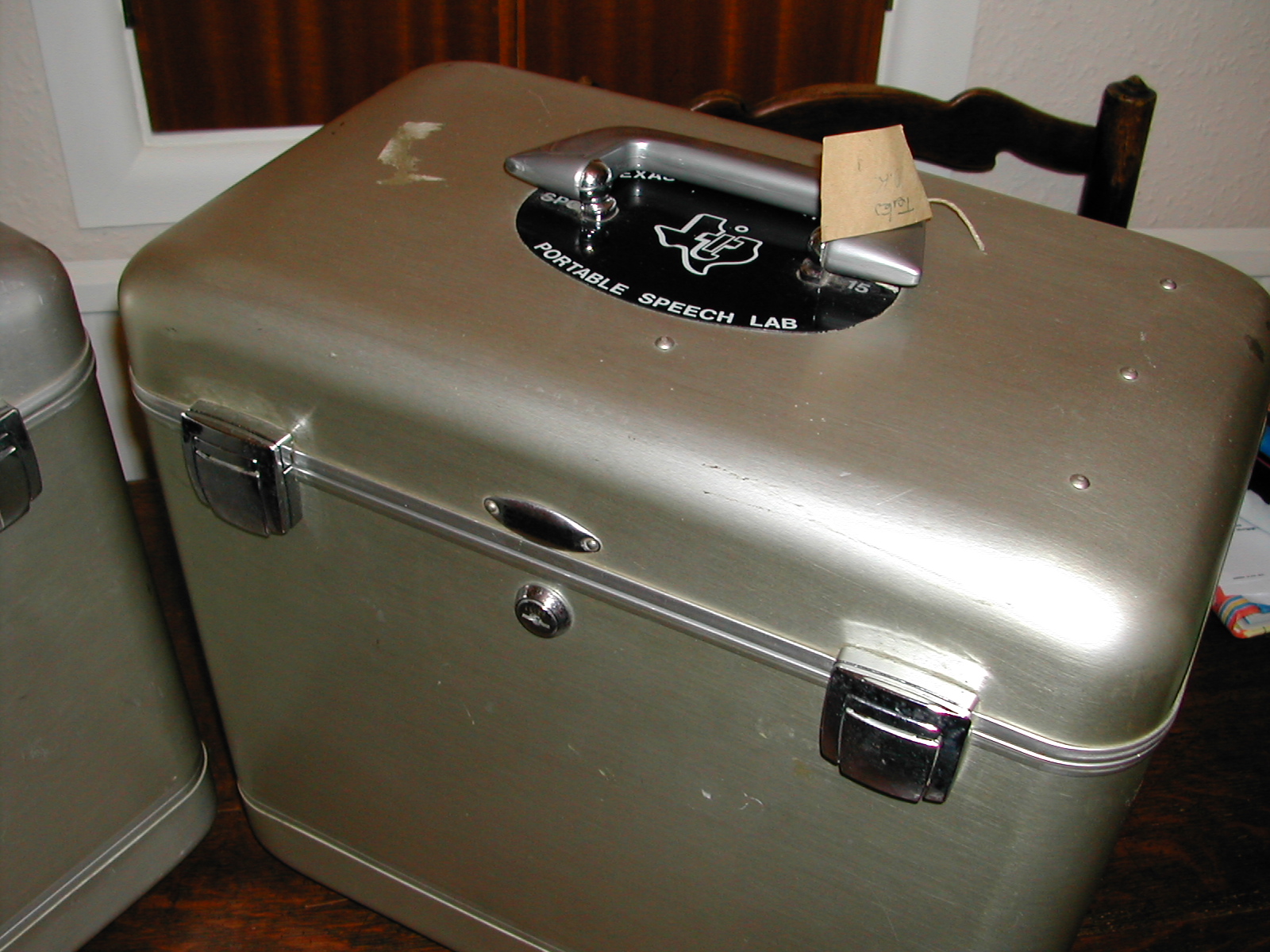
TI Portable Speech Lab
The Texas Instruments Portable Speech Lab system, also known as PASS – Portable Analysis and Synthesis System, translates speech into pitch-excited linear predictive codes (LPC) in real time. The system enables editing of the LPC data, immediate playback of recorded speech for instantaneous review of the sound it will have in the final product, and provides rapid storage of digitised speech into EPROM or uploading to a computer over an RS-232 interface. The system is self-contained in a portable metal carrying case, and is compatible with TI’s TMS 5100, TMS 5110, TMS 5200 and TMS 5220 LPC speech synthesis chips. The system was also available later repackaged into a desktop case and marketed as the "SDS50 Speech Development System" (the same case was also used for a TMS 320C2x Emulator system - some details of the case are included in this manual).
LPC is a compression technique that models the human vocal tract, and is described in many of the documents referenced here. The system converts speech to LPC by first converting the signal from analogue to digital then using digital signal processing techniques. The resulting LPC data is then coded to further reduce the bit-rate in accordance with the coding tables stored in ROM in the selected target speech synthesis device.
An example of the audio quality that can be achieved by the system can be played here (ignore the clicks and buzzes between the phrases; the audio was captured rather crudely using the Windows Sound Recorder). The two systems I acquired were used by a company that recorded station names for the British Rail automated announcement system, and these station names from the London area and South West England were found on an EPROM that was rattling around loose in the bottom of one of the cases.
(click on photos for larger views)
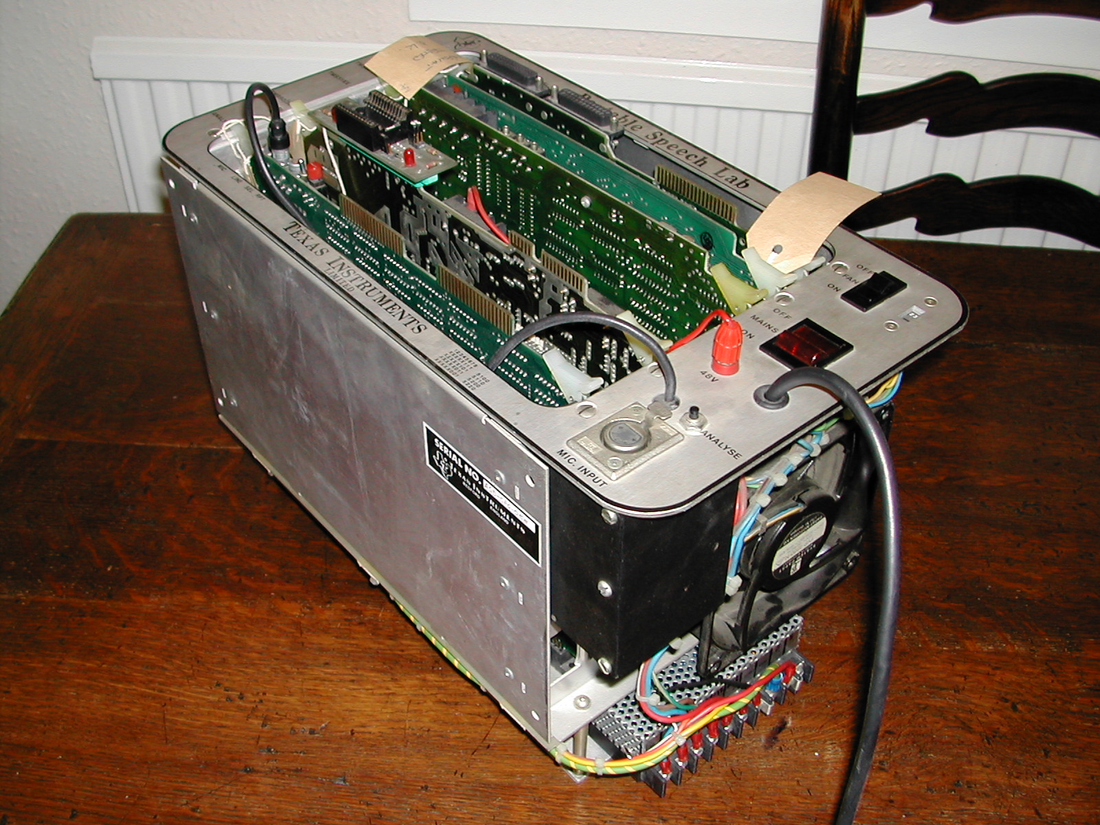
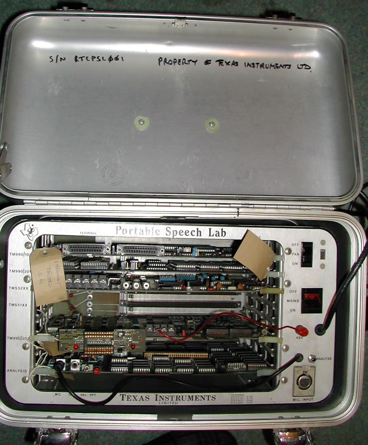
The system consists of five modules/boards of the TM 990 type. The components are a CPU module using a TMS 9900 processor, a memory expansion module to hold up to twelve seconds of speech parameters in RAM and program code in EPROM, a speech synthesis module for audio output, an EPROM programmer module and a real-time speech processor module. All the modules are standard TM 990 parts except for the speech processor, which was custom designed for this system.
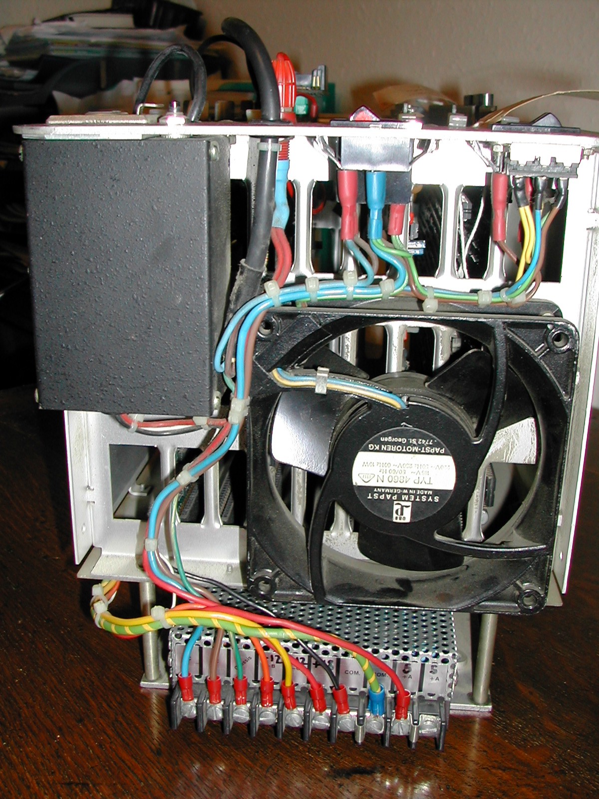
The modules are fitted in a card cage which, along with a mains power supply and cooling fan, are securely installed in a portable metal carrying case. The cooling fan has a separate on/off switch on the front panel to enable it to be temporarily switched off to reduce acoustic noise during a recording session.
The system provides the following interfaces:
CAUTION! The following information is largely derived from experimentation with the system and from various documentary sources. Be aware that it may contain errors.
In compiling this information, thanks are due to:
| LPC Compression | |
| Target speech synthesis chips supported: | TMS 5100, TMS 5110, TMS 5200, TMS 5220 |
| LPC data format: | Pitch-excited LPC-10 |
| Power Supply | |
| Input voltage: | Autoranging 115 to 230V ac Note: The cooling fan has a separate 115/230V supply selection switch on the front panel. |
| Output voltages: | +5V, ±12V dc +48V dc EPROM programming supply |
| RS-232 Port P2 (Control Terminal) | |
| Data format: | 7-bit data, even parity, 2 stop bits, no flow control |
| Baud rate: | 2400, 9600 Baud, selectable by DIP switch |
| RS-232 Port P3 (Remote Computer) | |
| Data format: | 7-bit data, even parity, 2 stop bits, no flow control |
| Baud rate: | 110, 300, 600, 1200, 2400, 4800, 9600, 19200 Baud, selectable by menu at time of data transfer |
| Microphone Input (XLR connector can be switched between microphone input and Line input using switch behind front panel) | |
| Microphone type: | Dynamic (moving coil) |
| Impedance: | 600 Ω (can be switched between high and low impedance using switch behind front panel) |
| Connector: | XLR 5-pin male connector on front panel, pins 2 (signal) and 3 (shield) |
| Line Input | |
| Signal level: | 1V pk-pk |
| Connector: | RCA plug on Speech Analysis module |
| Audio Output - Speaker | |
| Speaker impedance: | 8 Ω |
| Connection: | Screw terminal blocks T2(-) and T1(+) on TMS 52XX module |
| Audio Output - Line | |
| Signal level: | *** ? *** |
| Connection: | 2.5mm mono jack plug connector J3 on TMS 52XX module |
| EPROM Programming | |
| EPROM types supported: | |
| (with TM 990/514 personality card fitted to TM 990/302 EPROM programming module): | TMS 2708, TMS 2716 |
| (with TM 990/515 personality card fitted to TM 990/302 EPROM programming module): | TMS 2508, TMS 2516, TMS 2532 Note: TMS 2532A (with an "A") EPROMs do NOT work – they have a lower programming voltage than the TMS 2532 devices (21V as opposed to 25V) and will not program correctly (and may be damaged). |
Connect an RS-232 terminal to port P2 (the left-hand RS-232 port) on the TM 990/101 module. Set the terminal to 9600 Baud, 7-bit data, even parity, 2 stop bits, no flow control.
Note: The Baud rate for port P2 is set by the ID switches on the TM 990/101 module.
If speech data is to be upload/downloaded between the system and a terminal or computer, connect the terminal or computer to port P3 (the right-hand RS-232 port) on the TM 990/101 module. Set the terminal/computer to 7-bit data, even parity, 2 stop bits, no flow control; the Baud rate is specified at the time of upload/download.
(If using a desktop PC, connecting the on-board serial port to port P2, and a USB serial adaptor to connect to port P3, works fine.)
Connect the microphone to the XLR connector on the front panel.
Connect the speaker to terminal blocks T1 and T2 on the TMS 52XX module.
Ensure switches 6 – 8 of the edge-mounted DIP switch on the Speech Analysis module are set according to the speech synthesiser chip type to be used.
[Query: LED on processor module flashes if TMS 5220 board is not fitted?]
The system supports two operating modes, selected by an ID switch on the TM 990/101 module:
The remainder of this document relates to terminal mode unless stated otherwise.
Check that the mains voltage selection switch on the front panel is set to the local mains voltage.
Set the Fan switch on the front panel to ON.
Power-on the system by setting the Mains switch on the front panel to ON, then toggle the RESET switch on the /101 module. The system responds with the following message on the terminal:
**** 52XX PASS SOFTWARE VERSION 3.0 ****
COPYRIGHT (C) TEXAS INSTRUMENTS INCORPORATED
**** CHIP TYPE BEING USED IS 5220 ****
[]_
Note: The speech chip type shown ("52XX"/"5220" in the above example) depends on the setting of the edge-mounted DIP switch on the Speech Analysis module.
Power-off the system by setting the Mains switch on the front panel to OFF. All speech data that has not been download or written to EPROM will be lost.
The system supports UPPER-CASE input only.
It is not necessary to press <Return> after entering a command.
To see a list of the commands supported, enter any character that is not a valid command at the command prompt (so enter ? for example), and answer Y to the HELP? (Y/N) prompt.
Replays the current phrase.
If no phrase is currently stored, the system gives a short beep.
Records a new phrase and processes it into LPC data. After entering the command, recording starts when the Analyse button on the front panel is pressed, and stops either when the button is released or the maximum recording time of approximately 12 seconds is reached. If a phrase was successfully recorded, the recorded phrase is then repeated. If a phrase was not successfully recorded (microphone too close or too far away), a short beep is given.
After the command has been entered, but before pressing the Analyse button, pressing the RPT button on the Speech Analysis module repeats the last phrase. The RPT button appears to be inactive at all other times.
The (A)nalyse command doesn’t work if chip type set to 51xx on DIP switch on Speech Analysis module and the unit is fitted with a 52XX board. The system just hangs.
Enables the following analysis parameters to be modified:
[]S
4 MS HEX SILENCE THRES. (DEFAULT=0040) =>
4 LS HEX SILENCE THRES. (DEFAULT=0000) =>
4 HEX PEAK THRES. (DEFAULT=0030) =>
4 HEX PITCH RANGE BOTTOM? (DEFAULT=0019) =>
ENTER 0 OR 1. 1=FLAT TABLE. (DEFAULT=0001) =>
4 DECIMAL RMS NOISE THRESHOLD. (DEFAULT=0000) =>
Not yet sure what each parameter actually does ...
Sets the start and end frames within the current phrase over which other operations are performed.
[]B
ENTER TOP FRAME (DEFAULT=007) =>
ENTER BOTTOM FRAME (DEFAULT=078) =>
Not entirely sure how this is used or which other commands it is used with ...
If the command is entered and no phrase is currently stored, an error is displayed:
*** WARNING - FR IS NOT PRESENT ***
Display a confirmation prompt and returns to the TIBUG monitor.
[]Q
DO YOU WISH TO QUIT? (Y/N) Y
?
When the system is fitted with a TMS 52XX module, sets the playback volume level.
[]V
INPUT VOLUME FROM 0 TO 3F :
The default volume level is about >9. A lower value is louder, a higher value quieter.
This command does not affect the LPC data output. It controls an amplifier on the TMS 52XX module, not the TMS 52XX chip itself.
Programs an EPROM using the TM 990/302 module.
The command actually seems to support reading the contents of an EPROM and verifying an EPROM against memory as well. Not sure what the concept of a 'codepack' is as mentioned in one of the options.
[]P
FUNCTIONS: R=READ, P=PROGRAM, V=VERIFY
DEVICES : 2508,2708,2516,2716,2532
INPUTS : ALL INPUTS ARE IN HEX
MODES : B=BYTE OR W=WORD
*** BYTE MODE TRANSFERS DATA BYTE BY BYTE ***
*** WORD MODE TRANSFERS MS OR LS BYTES ONLY ***
IS THIS A NEW EPROM? (Y/N): Y
ENTER REQUIRED FUNCTION (R/P/V): P
1. ENTER DEVICE TYPE (DEFAULT = 2532) =
2. ENTER BYTE/WORD MODE (DEFAULT = B) =
3. ENTER CODEPACK START ADDRESS (DEFAULT = B4AA) =
4. ENTER EPROM PHRASE START ADDRESS (DEFAULT = 0000) =
5. ENTER NO. OF BYTES TO BE OPERATED ON (DEFAULT = 0167) =
*** ERASE CHECK STARTED ***
ENTER NO. OF PROGRAMMING LOOPS (DEFAULT = 0032) =
*** PROGRAMMING STARTED ***
Enables a phrase to be concatenated with other words or phrases so that it can be heard in context using the (H)ear Concatenation command.
Not sure how concatenations are set up. A hex value can be entered for each address, delay and SRC/INC field, with the space bar being used to progress through the fields. Press Q to quit back to the command prompt.
[]M
NEW CONCATENATION? (Y/N): Y
*** CONCATENATION TABLE ERASED ***
ADDRESS: FFFF=STOP, FFFE=RECENTLY ANALYZED PACKED PHRASE
SOURCE : 00=PACKED PHRASE, 01=302 EPROM, 11=MAIN MEMORY.
NUMBER ADDRESS ________ DELAY ________ SRC/INC _______
0001 FFFF 0000 0000
Presumably plays a concatenated phrase.
Lists the LPC data frames for the current phrase. Details of the parameters presented are given here.
The "T-->" and "B-->" lines are the top and bottom frame markers associated with the (B)oundary Set command.
[]L
# ERGY CE P K1 K2 K3 K4 K5 K6 K7 8 9 0
001 0060 01 00 11 01 06 05
002 0066 01 00 08 02 05 05
T-->
003 0059 02 00 11 03 05 05
004 0061 02 00 11 02 05 05
005 0062 02 00 11 02 05 05
006 0055 02 00 14 02 06 06
007 0068 02 00 09 03 05 05
008 0057 02 00 12 03 05 05
009 0065 01 00 09 02 05 06
010 0062 01 00 10 02 06 06
011 0039 01 00 16 02 04 05
012 0131 10 39 21 12 07 05 06 06 06 3 3 4
013 0882 14 45 22 20 03 08 03 03 08 3 3 5
014 0573 13 46 21 19 04 06 03 03 08 4 4 5
015 0505 13 47 21 20 05 06 03 01 07 4 3 5
016 0196 12 49 22 13 07 04 03 04 07 4 3 3
017 0072 09 52 22 13 07 04 04 05 07 4 3 2
018 0146 02 00 00 06 08 07
019 0066 02 00 11 04 06 07
020 0056 02 00 15 05 07 05
021 0069 02 00 09 04 06 05
022 0051 02 00 15 03 05 05
B-->
023 0069 01 00 08 01 05 05
024 9585 01 24 27 78 03 75 85 26 17 2 4 8
Presents a series of sub-commands for editing the current phrase.
[]E
COMMANDS: C,G,H,I,Q,R,W,X,-,<,>,ESC-1..9
INPUT FRAME NUMBER (DEFAULT = 003) :
T-->
003 0059 02 00 11 03 05 05
The sub-commands are:
<Return> steps to the next frame.
The columns of data are the same as those used with the (L)ist Phrase command. Typing in new numeric values steps from field to field and then steps to the next frame. Pressing <Space> also steps from field to field, retaining the current value of each field. If an invalid 'K' parameter value is entered, the display steps down a line for entry of a valid value.
Not sure what the relevance of converting the data to serial, and the bit position is.
[]C
DEVICES : 2508,2708,2516,2716,2532
1. ENTER DEVICE TYPE (DEFAULT = 2532) =
2. ENTER BIT POSITION (0 THROUGH 7) => 0
CONVERT AND PROGRAM? (Y/N): Y
*** ERASE CHECK STARTED ***
ENTER NO. OF PROGRAMMING LOOPS (DEFAULT = 0032) =
*** PROGRAMMING STARTED ***
Outputs data to a remote computer connected to port P3 on the TM 990/101 module. The data is output in relocatable 990 tagged object code format. Not sure what the definition of a codepack is - a data block containing multiple phrases? Not sure of the difference between outputting to Computer or Terminal in the first option. Nothing is output if an IDT of just <Space> is specified. Note typo in first option!
[]O
TRANFER TO COMPUTER OR TERMINAL? (C/T): T
SET BAUD (1=110 2=300 3=600 4=1200 5=2400 6=4800 7=9600 8=19200): 8
ASR FLAG (1=CR DELAY, 2=INTER-CHARACTER GAP, 3=NO DELAY/PADDING): 3
SOURCE (1=LAST PHRASE, 2=MEM, 3=302 EPROM, 4=EXIT): 1
FILE IDT (SIX CHARACTER NAME ENDING IN SPACE):
If output to Computer is selected, the transfer times out after 30 seconds if no remote device is detected:
*** WARNING -- DEVICE OFFLINE !! ***
Presumably downloads and speaks a codepack from a remote computer connected to port P3 on the TM 990/101 module. Not sure what the definition of a codepack is.
[]D
SET BAUD (1=110 2=300 3=600 4=1200 5=2400 6=4800 7=9600 8=19200): 8
ASR FLAG (1=CR DELAY, 2=INTER-CHARACTER GAP, 3=NO DELAY/PADDING): 3
ENTER CODEPACK STORAGE ADDRESS (DEFAULT = D000) =
The download times out after 30 seconds if no data is received:
*** WARNING -- DEVICE OFFLINE !! ***
Speaks the phrase at varying speed, with 1 being normal speed, and 9 very slow speed.
Displays the following test information:
HEX CHECKSUM = 05CD
PRESS ANY KEY TO STOP.
LO=00030040 0000BC60 HI=000337C0 66E0CDC0 CRU=1111111111110011
The checksum varies between the two systems I have tested. Mine gives a checksum of 8F09.
The LO and HI values displayed relate to the audio input and may be different to the values shown above. If you press and hold the Analyse button on the front panel and speak into the microphone, these values change.
The values LO and HI are read from >E000 to >E006 and >E400 to >E406.
With the CRU binary value displayed:
Retrieves packed phrase data from an EPROM.
On selecting the command, the system prompts for the:
On loading a phrase, the system displays the phrase information, speaks the phrase, then displays the QUIT? (Y/N) prompt. If just scanning for phrase data, the phrase information is displayed followed by the QUIT? (Y/N) prompt.
[]F
DEVICES : 2508,2708,2516,2716,2532
INPUTS : ALL INPUTS ARE IN HEX
MODES : B=BYTE OR W=WORD
*** BYTE MODE TRANSFERS DATA BYTE BY BYTE ***
*** WORD MODE TRANSFERS MS OR LS BYTES ONLY ***
1. ENTER DEVICE TYPE (DEFAULT = 2532) =
2. ENTER BYTE/WORD MODE (DEFAULT = B) =
3. ENTER START ADDRESS OF PHRASE (DEFAULT = 0000) =
SCAN PHRASE ONLY? (Y/N): N
*** PACKED PHRASE RETRIEVAL STARTED ***
*** LENGTH OF PHRASE = >00F6 BYTES ***
*** PHRASE START ADDRESS = >0000 ***
*** PHRASE END ADDRESS = >00F5 ***
*** NO. OF FR-FRAMES = >003B ***
*** NO. OF R-FRAMES = >0004 ***
*** VERIFY STARTED ***
*** TASK COMPLETE ***
QUIT? (Y/N):
Answering Y to the QUIT? prompt returns to the command prompt.
Answering N to the QUIT? prompt returns to the SCAN PHRASE ONLY? prompt and scans the EPROM for another phrase, starting at the EPROM address immediately after the last address used by the previous phrase. If the option is selected to scan and load a phrase, and a phrase has previously been loaded, the system responds:
*** ANALYSED PHRASE ALREADY EXISTS !! ***
DO YOU WANT TO SAVE CURRENT PACKED PHRASE? (Y/N):
[Need to explore the further combinations of options ...]
If an error is found in the stored phrase data, the following prompt is displayed:
*** ERRORS FOUND IN PHRASE !! ***
*** FILE RETRIEVAL ABORTED !! ***
QUIT? (Y/N):
This section is a 'reprint' from an article about the system that appeared in the magazine "Electronics" dated September 8, 1982.
Portable speech development system creates linear predictive codes
Operating in real time, this system allows immediate review and editing of LPC
parameters, eliminates delays in synthetic speech development
by Gene Helms and Steve Petersen, Texas Instruments Inc., Dallas, Texas
Long a science writer’s fantasy, talking machines have recently become feasible in consumer products and are appearing increasingly in business and industrial applications, thanks largely to compression techniques such as linear predictive coding, which models the human vocal tract. Yet although the sound of synthesised speech has improved markedly since its introduction – at least for a given amount of storage space – the process of converting speech into linear predictive codes has remained laborious.
A major drawback of LPC and similar speech-encoding systems has been the delay between the original recording of a speech sample – usually on magnetic tape – and its subsequent digitisation and replay. By the time the speech sample has been encoded and tested with the target synthesiser – the speech synthesiser that will be used in the final product – the original speaker is often not available should it prove necessary to retape the sample.
PASS, a new portable analysis and synthesis system, replaces cumbersome encoding techniques by translating speech into linear predictive codes in real time. Not only does PASS allow immediate playback of encoded speech for instantaneous review of the sound it will have in the final product, but it can also provide rapid storage of digitised speech into erasable programmable read-only memory.
Compatible with the TMS 5100, 5110, 5200 and 5220, which compose Texas Instruments’ present line of LPC speech-synthesis chips, PASS can reduce to minutes the time required to prepare encoded speech for ROMs and EPROMs. It also allows companies to keep their speech development in house, where they can be assured of confidentiality, and may even encourage the formation of independent speech-development laboratories.
What’s more, the system's portability means the hardware can be shared by different development teams within an organisation, and its operation is simple enough to enable even an unsophisticated user to encode and replay speech.
The basic stand-alone configuration for PASS (Figure 1) comprises a microphone, a loudspeaker, and the PASS unit itself. Such a system is capable of demonstrating speech encoding and playback through the target synthesiser. The encoded speech can be played back through the synthesiser at the push of a button.
Figure 1 PASS System Block Diagram
However, for saving encoded speech and editing the LPC parameters, a terminal must be added to the basic system so that operations can be performed under control of keyboard commands. The terminal is attached by means of an RS-232-C interface and enables the operator to list and edit the LPC parameters for pitch, reflection coefficients, and energy. Commands can be given for downloading the encoded speech into an EPROM chip by means of an optional built-in EPROM programmer. This method allows quick, efficient generation of vocabularies that can be used directly in a product or evaluated in a prototype system.
The PASS system can also be interfaced with a host computer that controls a speech data base. The data base can serve as an archive for encoded vocabularies; whenever words or phrases that have already been encoded are needed for another project, they can be retrieved easily, combined or edited, auditioned, and downloaded to EPROMs, all with the PASS unit.
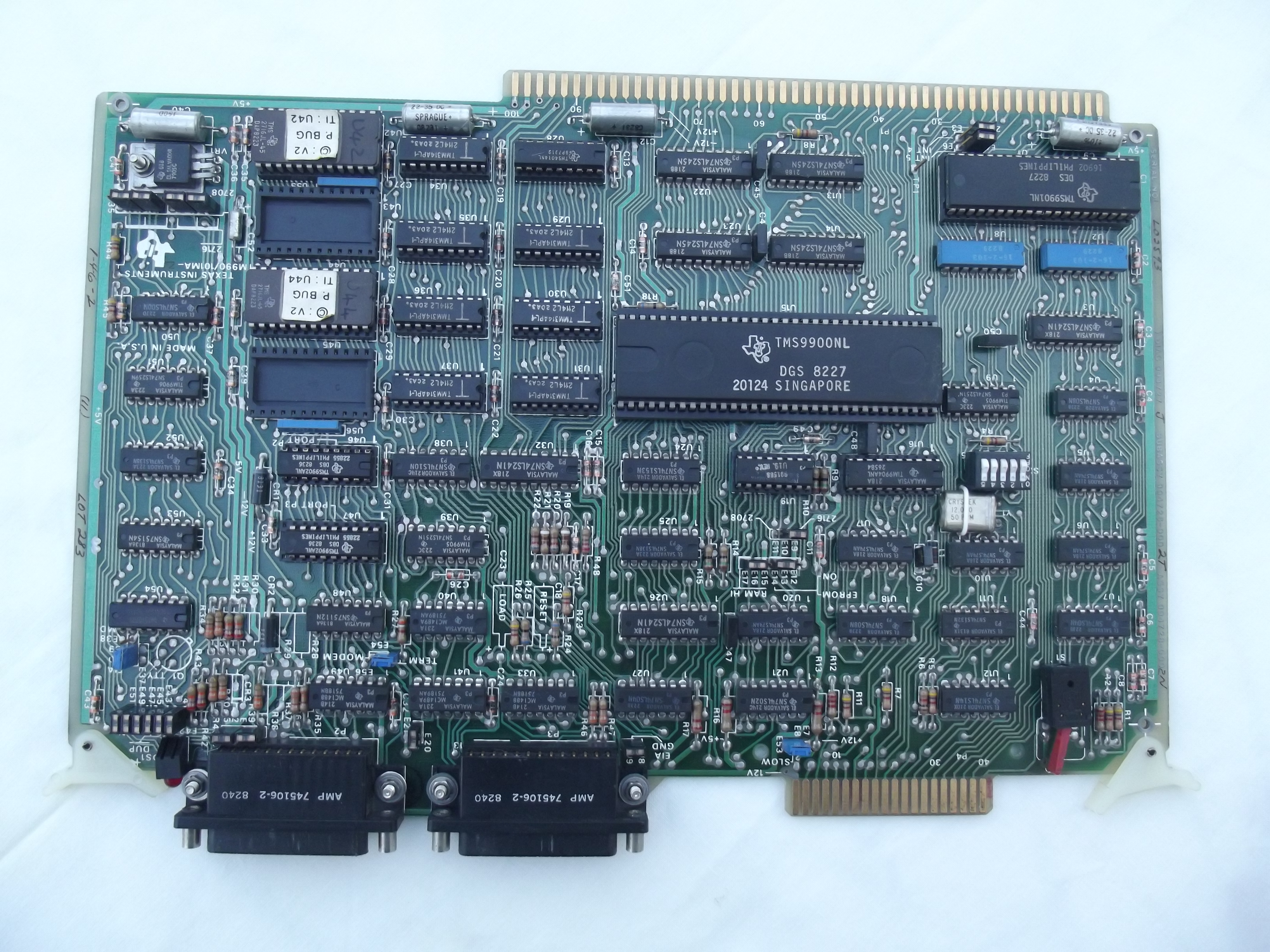
The system's capabilities derive from its blend of modular hardware design, including the use of a high-speed multiplier-accumulator, and special speech-processing algorithms embodied in the software. The PASS hardware consists of four major boards: one for a custom processor, the TM990/201-43 memory board, the TM990/101MA central processing unit board, and the fourth for the speech synthesiser. [Edit: plus the TM990/302 EPROM programmer board.]
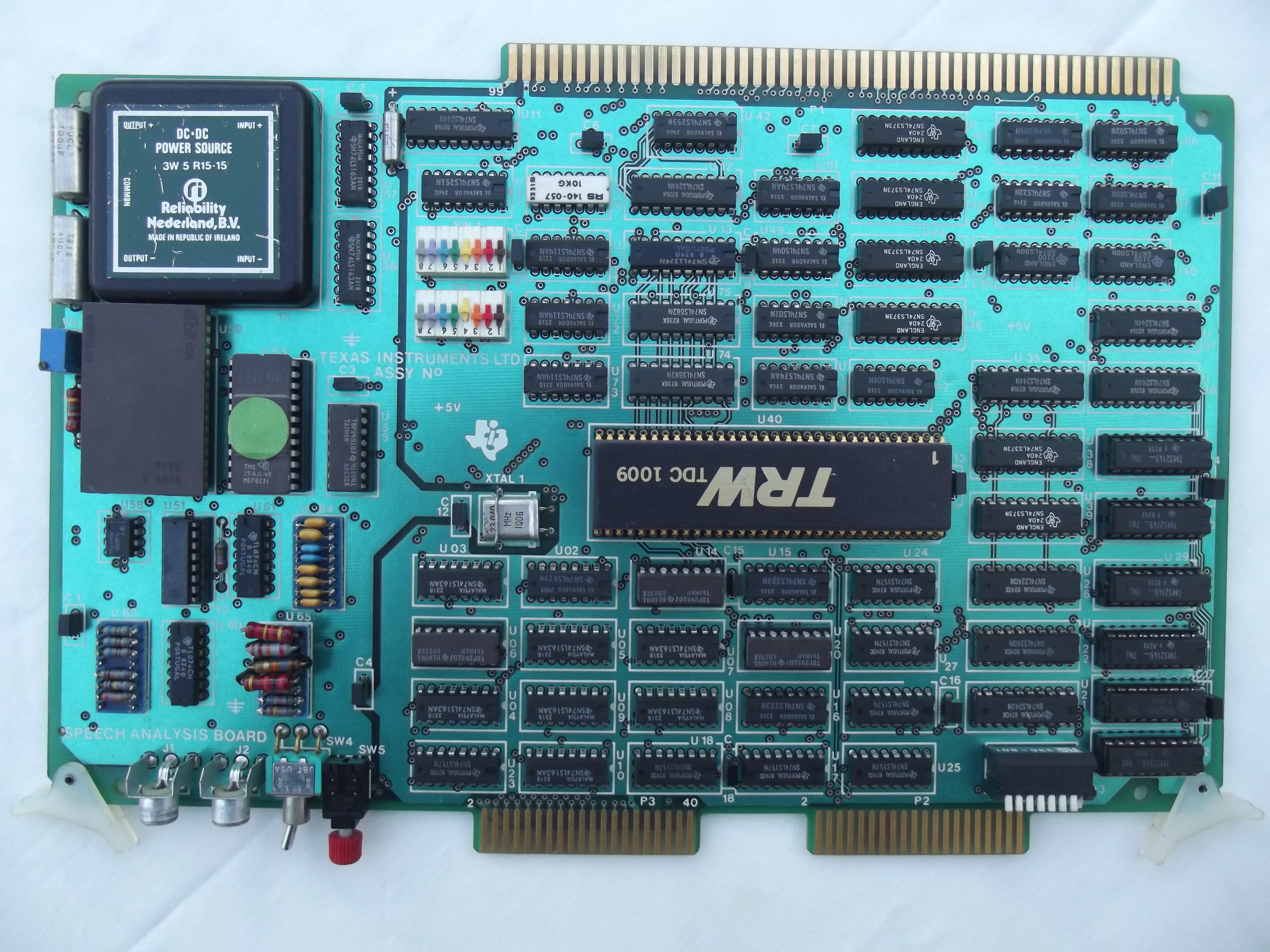
As shown in Figure 1, the flow of data is from the microphone input to the custom processor board, where the analogue signals are converted into digital autocorrelation coefficients, which reflect the degree of periodicity of the waveform being analysed. The custom processor board stores these coefficients on the memory board in 25-millisecond segments, or frames. While the custom processor board is dealing with a frame of speech, the CPU on the TM990/101MA processor board takes the coefficients stored in memory from the previous frame and transforms them into parameters that can be employed to control the speech synthesiser. These parameters may be activated through the synthesiser to create speech directly or downloaded into EPROM.
The functions performed by the custom processor and the CPU are the most critical aspects of the system. The purpose of the first is to generate two sets of autocorrelation coefficients that represent the frequency spectral characteristics of a 25-ms speech segment. One set of autocorrelation coefficients is used for LPC spectral analysis, while the other is used to track the pitch of the input speech. The autocorrelation coefficients computed from the digitised speech waveform are defined as:
where s(n) is the nth digital speech sample and M is 200, the number of speech samples in the frame. In order to obtain two sets of coefficients, the analogue input is first divided between two different filter paths, as is illustrated in Figure 2.
Figure 2 Custom Processor Board
The first set of autocorrelation coefficients, that for LPC spectral analysis, is derived by first passing the speech input signal through a Hamming-window circuit. The Hamming-window circuit is a multiplying digital-to-analogue converter that imposes a cosine-bell envelope on the 25-ms frame of speech to attenuate the signal at either end of the frame. Thus the end points of each frame are kept low in amplitude to smooth the contours of the synthesised speech waveform.
The output of the Hamming-window circuit is then sent through a low-pass, 4-kilohertz filter in order to remove any high-frequency noise, including aliasing (that is, spurious signals generated by sampling). The spectral information that is necessary to reproduce human speech is contained within this 4-kHz band.
At the same time, the original input is sent through another low-pass filter with an 800-hertz cutoff frequency. The output of this path is used to create the other set of autocorrelation coefficients, those employed for tracking the pitch of the input speech.
The outputs of both filters are sent to the data selector, a multiplexer that feeds them alternately to a hybrid 12-bit linear analogue-to-digital converter. This converter samples each of the signals at an 8-kHz rate by successive approximation.
The output of the a-d converter – 96 kilobits per second for each signal – is sent to another data selector which stored the digitised data in one of two high-speed random-access memories. The data selector also multiplexes the digitised data, switching between the two memories every 25 ms to create the frames. Thus the memories act as two separate buffers, each storing a 25-ms frame of speech.
While one buffer is being loaded, the contents of the other are taken by a third data selector and fed to a high-speed multiplier-accumulator, where they are translated into autocorrelation coefficients under the control of the index-generation logic. This process results in the calculation of 140 autocorrelation terms for each frame of speech: 12 coefficients are created for the subsequent LPC spectral analysis, and 128 are computed from the 800-Hz band for use in the pitch analysis. These coefficients are transferred by direct memory access to the system’s main store, the 201-43 memory board.
As data is being sent to one buffer of the main store, the CPU takes stored information from the alternate buffer. In effect, the CPU works in opposite cycles to the customer processor. The CPU, programmed in assembly language to perform in real time, goes through four functional computations to produce the parameters needed by the synthesiser (Figure 3).
Figure 3 Software Pitches In
In its first computation, the CPU takes the set of 128 coefficients and performs an autocorrelation pitch analysis to obtain one pitch parameter for each frame. This parameter is used by the synthesiser to determine whether the synthesiser filter should be excited by white noise which produces an unvoiced sound – which in humans does not involve the vocal cords – such as "h", "s", "f", or by a periodic excitation, which results in a voiced sound such as the "ee" in "speech". For voiced sounds, the fundamental frequency is also calculated in the pitch analysis, determining the pitch of the synthesised sound.
A second software routine determines the reflection coefficients that will shape the synthesiser’s lattice filter, which models the vocal tract through which the voiced or unvoiced excitation passes. This routine uses the spectral set of 12 autocorrelation coefficients computed by the custom processor board to produce 10 reflection coefficients. The algorithm used by the processor is based on the work of two French mathematicians, J. Le Roux and C. Guéguen of the Ecole Nationale Supérieure de Télécommunications in Paris.
The Le Roux-Guéguen algorithm is what makes it possible to use a general-purpose processor like the TMS9900 CPU to do the needed calculations. With earlier algorithms such as the Levinson recursion or direct-matrix-inversion techniques, floating-point calculations are required to handle the wide range of intermediate values that can result during the computations. The advantage of the Le Roux-Guéguen algorithm is that it yields intermediate values with magnitudes less than 1, thus permitting fixed-point calculations to arrive at the same reflection coefficients.
The third computation performed by the CPU is a calculation of the energy of the input signal. This calculation is used to determine the gain needed by the synthesiser to reproduce a sound with the same volume as the original speech. Once this routine is completed, the three parameters needed to drive the synthesiser – pitch, reflection coefficients, and energy level – have been determined.
All three of these routines are performed in real time as the speech signal is being input by the speaker. The speech parameters that are produced require less than 7 kb of memory per second for storage, as compared with 64 to 96 kb/s for direct waveform encoding. As a result, the LPC compression techniques substantially reduce the amount of memory required to store the digitised speech and make possible a portable system that uses only RAM storage.
The maximum phrase length that the PASS can accommodate is 12 seconds. That limit is set by the 16-k bytes of RAM available.
A fourth routine goes through all of the stored intermediate parameters frame by frame and encodes them to correspond with the decoding table that is stored on the synthesiser chip. Once this is done, the parameters can be formed into a bit stream and sent to the synthesiser. After the encoded speech has been readied for the synthesiser, it requires approximately 1.8 kb of memory per second of speech. This represents a 50-to-1 reduction in storage space over the directly digitised waveform.
In many cases, the user will find it possible to employ the PASS system primarily for speech capture without needing to edit the captured speech, since the facility of intermediate playback through the processor makes it simple to record a word or phrase again if it is not satisfactory the first time. However, the commands available when the PASS system is attached to a terminal allow EPROM programming and sophisticated speech-editing functions, including the ability to create any new sounds that are theoretically possible for the human vocal tract.
The commands available in the command menu are shown in Table 1. For example, striking P on the terminal keyboard calls up a menu of commands for EPROM programming. Pressing A – for analysing another phrase – readies the PASS system to record a new phrase. Once the phrase is captured, it can be played immediately by striking the R key in order to invoke the replay phase command.
Table 1 PASS Speech-Synthesis System Commands
| Command | Action |
| R | Replay |
| A | Analyse another phrase |
| S | Set analysis parameters |
| Q | Quit and return to TIBUG debugger |
| V | Volume |
| P | Program erasable programmable read only memory |
| M | Modify concatenation sequence |
| H | Hear concatenation sequence |
| L | List phrase parameters |
| E | Edit phrase parameters |
The next likely step when editing would be to employ the commands for listing or editing phrase parameters. When either command is invoked, the LPC parameters are displayed on the screen, as shown in Figure 4. The energy parameter (ERGY) is listed after the frame number, followed by the gain parameter (CE), the pitch parameter (P), and the reflection coefficients, K1 through K10.
Figure 4 LPC Parameters for the Word "Help"
For a novice, the parameters that are simplest to edit are energy and pitch. If some syllable or sound should receive more emphasis, the energy value can be suitably increased. Pitch can be altered similarly.
The more sophisticated user can edit the reflection coefficients, which may be used not only to edit recorded speech but to create sound effects. By employing the hear-concatenation sequence command, the user can play an edited phrase in context with other words or phrases. If, for example, the word "two" is to be used to tell time – such as "one thirty-two" or "two thirty-one" – its inflection will differ according to its position in the phrase. The modify-concatenation sequence command permits the user to specify the order of phrases, which can then be evaluated by means of the hear command.
| >0000 - >0FFF | EPROMs on processor module |
| >2000 - >9FFF | EPROMs on /201 module |
| >A000 and >A002 | TMS 5220 |
| >B000 - >EFFF | RAM on /201 module |
| >E000 - >EFFF | ADC on Speech Analysis module (parallel to RAM?) |
| >F000 - >FFFF | RAM on processor module |
| >0040 | ID DIP switch on /101 module |
| >0080 | TMS 9902 RS-232 port P2 on /101 module |
| >0180 | TMS 9902 RS-232 port P3 on /101 module |
| >0100 | TMS 9901 on /101 module |
| >0540 | TMS 52XX module |
| >1000 | Speech Analysis module |
| >1700 | EPROM Programmer module |
Links to specifications and documentation for many of the modules are available here.
The DIP switches on the TM 990/101 module control the system operating mode and port P2 Baud rate as detailed in the following table.
| Switch Position | Setting | Action | |
| 1 | ON | Boot into speech application | |
| OFF | Boot into TIBUG | ||
| With Switch Position 1 ON | With Switch Position 1 OFF | ||
| 2 | ON | Initialises system into terminal mode | No effect |
| OFF | Initialises system into standalone mode | No effect | |
| 3, 4, 5 | OFF – OFF – OFF | Sets port P2 to 110 Baud | No effect |
| OFF – OFF – ON | Sets port P2 to 300 Baud | No effect | |
| OFF – ON – OFF | Sets port P2 to 600 Baud | No effect | |
| OFF – ON – ON | Sets port P2 to 1200 Baud | No effect | |
| ON – OFF – OFF | Sets port P2 to 2400 Baud | No effect | |
| ON – OFF – ON | Sets port P2 to 4800 Baud | No effect | |
| ON – ON – OFF | Sets port P2 to 9600 Baud | No effect | |
| ON – ON – ON | Sets port P2 to 19200 Baud | No effect | |
Switch set to ON reads as 0.
Switch set to OFF reads as 1.
Note: On my system the DIP switches are a little "sticky" and often require a bit of fiddling to make them register the correct position.
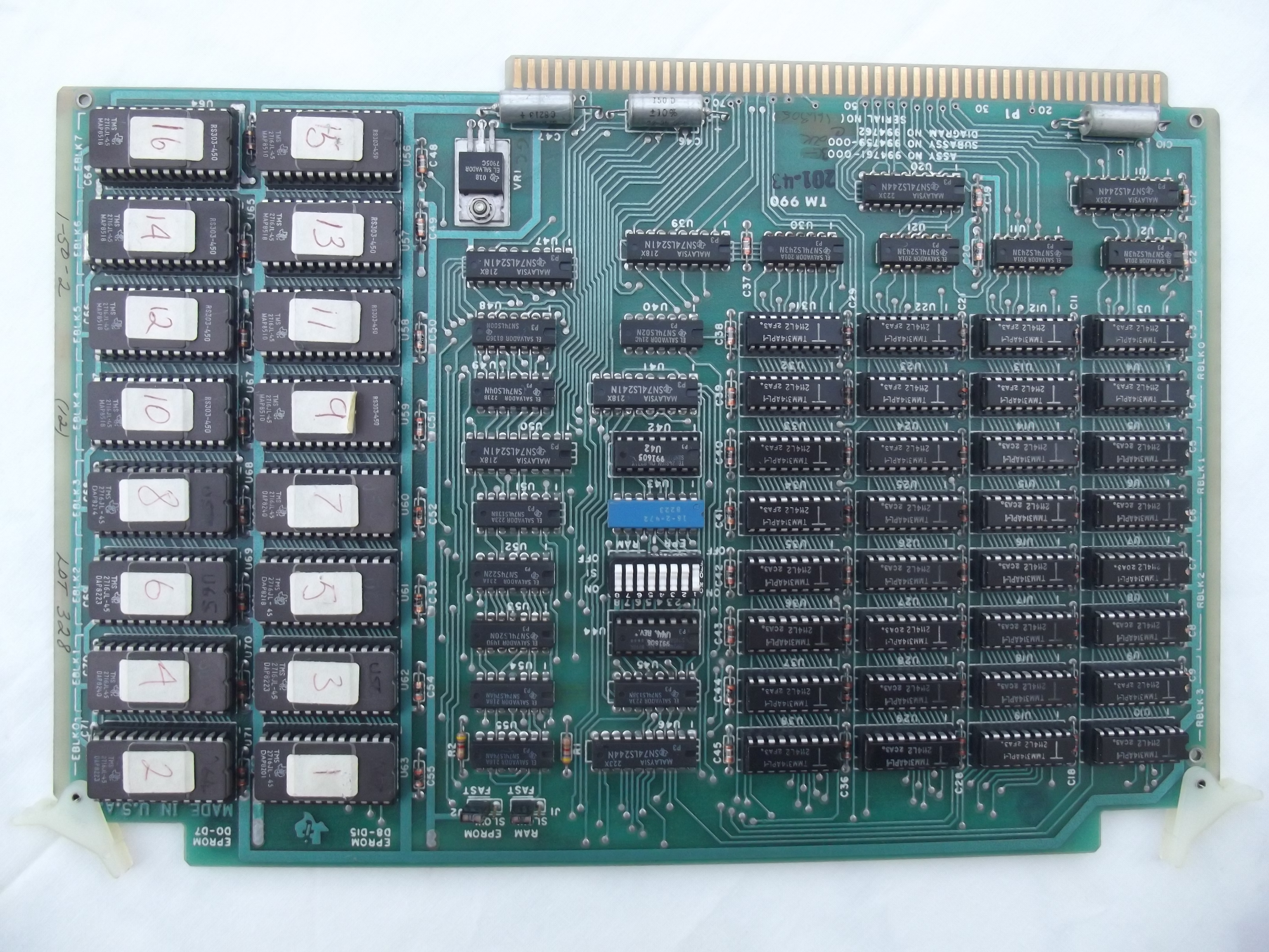
32 off TMM314APL-1 RAMs (= 16K bytes)
16 off TMS2716 EPROMs (= 32K bytes)
PROMs – "991605 U42" and "991606 U44 REV. *"
Jumpers J1 and J2 both set to FAST.
DIP switch – position 1 OFF, 2-8 ON (RAM at >B000 - >EFFF, EPROM at >2000 - >9FFF).
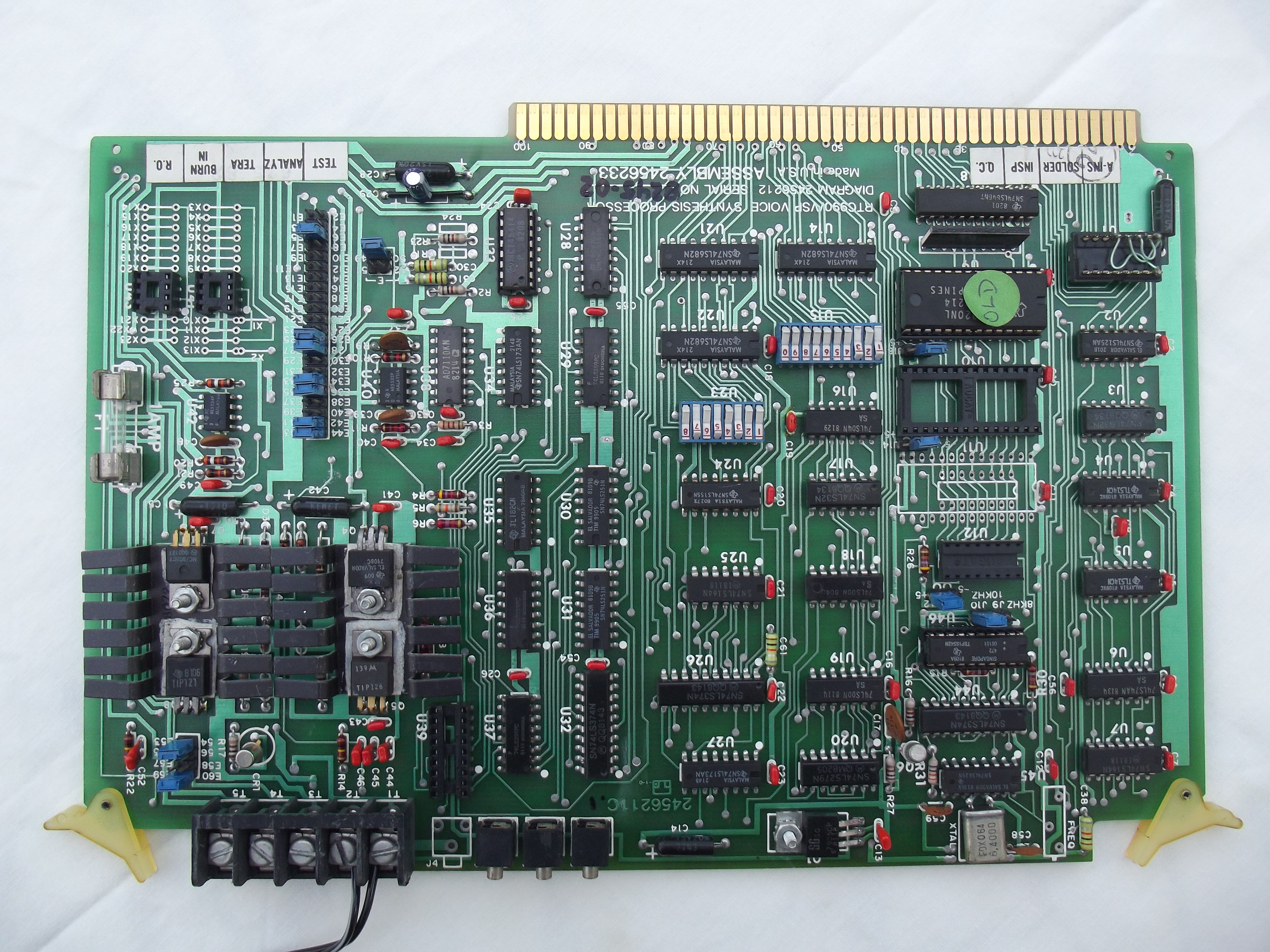

+/-8V regulator outputs fed to Vaux and Vbatt lines on backplane. Supplies for the Speech Analysis module.
Speaker output on screw terminal blocks T2(-) and T1(+). Speaker may buzz at power on until the processor module is reset.
J3 gives audio line output.
U10, U11 and U12 appear to be sockets for fitting TMS 6100 (28-pin 0.6" footprint) and TMS 6125 (16-pin 0.3" footprint) voice synthesis memories. A jumper adjacent to each socket is used to hard-wire the /CS pin for that socket either permanently enabled or permanently disabled.
U15: 10 MSbits of the TMS 5220 memory address decoding, with switch position 1 being the MSbit and switch position 0 being the LSbit. With switch positions 1 and 3 OFF and the rest ON, this gives the memory address of binary 1010 0000 00xx xxxx or >A000.
U23: Module CRU software address decoding, with switch position 1 equating to address line A3, and switch position 7 equating to address line A9. Switch position 8 is not connected. With switch positions 3, 5 and 7 OFF and the rest on, this gives the CRU software base address of binary (000)0 0101 010x xxxx or >0540.
J9 (8 kHz/10 kHz): Sets the playback sample rate of the speech synthesiser chip. Changing the jumper while powered-on sometimes seems to require a power-cycle or the system hangs. IT DOES NOT SET THE RECORDING SAMPLE RATE, WHICH SEEMS TO BE STUBBORNLY FIXED AT 10 KHz.
J11/12, J13/14, J15/J16 (-5V/+5V): Hard-wire the /CS inputs to voice synthesis memory sockets U12, U11 and U10 respectively. When set to the -5V position, /CS is active.
E49/50, E51/52: selects the output of filter A or B respectively in dual tuneable low-pass sampled data filter U33 and feeds to jumpers E5/6 and E13/14. *** which achieves what???? ***
E41/42, E43/44: no speaker output with these jumpers removed.
E33/34, E35/36: no speaker output with these jumpers removed.
E25/26, E27/28: *** don’t seem to do anything???? ***
E53/54, E59/60: some sort of output filter? Speech not as good with this jumper removed.
E5/6: no speaker output with this jumper removed.
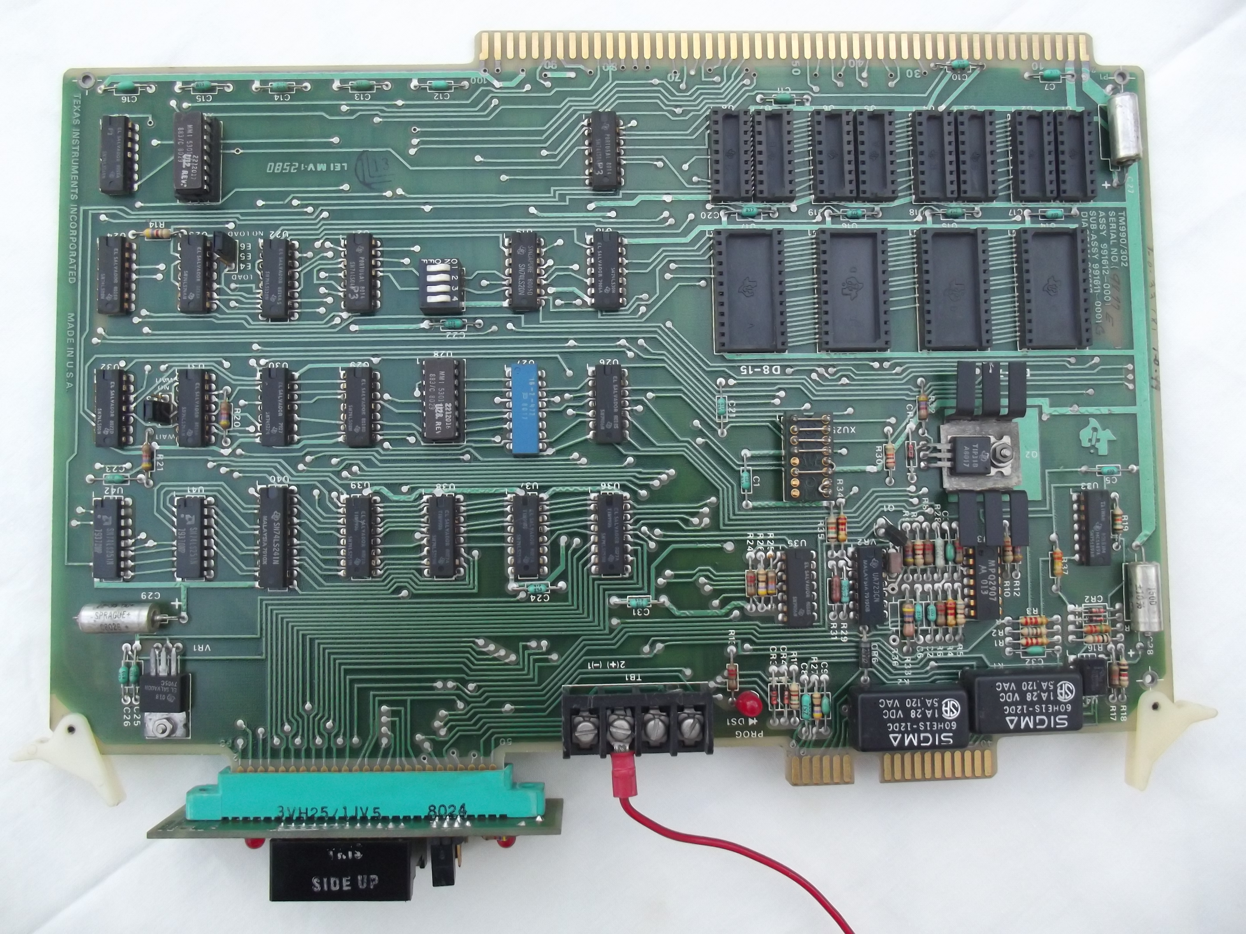
This is a standard TM 990/302 module with a TM 990/515 EPROM Programming Personality module for programming 2508, 2516 and 2532 EPROMs. No on-board RAM or EPROM memory expansion is fitted.
The module has a flying lead to the EPROM programming supply connector on the front panel.
SW1 – SW4: all OFF.
CRU bit 5 is the 20 or 25ms frame clock.
SW1 (nearest PCB edge connector) and SW2: appear to be CRU base address, with SW2 position 1 being the MSbit and SW1 position 8 being the LSbit. With all switches ON except for SW2 position 4, this gives the default CRU base address of binary 0001 0000 0000 0000 or >1000.
Switches 6 – 8 of the edge-mounted DIP switch specify the target speech synthesiser chip type. The switch settings are shown on the adjacent printing on the chassis front panel ('1' = switch ON) and are reproduced below.
| Switch 6 – 8 Setting | Target Speech Synthesiser Chip Type |
| ON – ON – ON | TMS 5100 |
| ON – OFF – ON | TMS 5110 |
| OFF – ON – ON | TMS 5200 |
| OFF – OFF – ON | TMS 5220 |
The card cage is an 8 slot version. The backplane is a late version with ‘power present’ LED indicators.
The system contains a modified version of the TIBUG monitor in EPROM. TIBUG is described on this page.
The TIBUG monitor in the PASS system contains an additional command, 'G', which is a 990 tag format loader which recognises the standard tags with the exception of the 'B' tag which seems to load data byte-by-byte instead of word-by-word.
The system contains a basic self-test routine in EPROM at address >09B0. This has to be run from the TIBUG monitor using the 'R' command to specify the start address then the 'E' command to execute the routine. The output of a successful test is shown below.
**** 52XX PASS SOFTWARE VERSION 3.0 ****
COPYRIGHT (C) TEXAS INSTRUMENTS INCORPORATED
**** CHIP TYPE BEING USED IS 5220 ****
[]Q
DO YOU WISH TO QUIT? (Y/N) Y
?R
W=F27E
P=7CAA 09B0
?E
MEMORY TEST DONE
201 RAM TEST PASSED
201 RAM TEST COMPLETED
FRAME CLOCK CHECKED AT; 20 MS IN HIGH STATE
FRAME CLOCK CHECKED AT; 20 MS IN LOW STATE
PRESS REPEAT SWITCH
REPEAT SWITCH TEST PASSED
PRESS MIC. SWITCH
MIC. SWITCH TEST PASSED
TMS5220 VSP SELECTED
?
I was excited to receive an e-mail from Steve Petersen who designed much of the PASS system and co-wrote the magazine article reproduced here. Steve came across this web page and described the system as "one of the most fantastically interesting projects I ever designed/built during my career".
Steve was able to supply the following photos/papers/documents:
Steve was also able to answer some questions (Steve's replies in-line in green):
TMS 5220 Voice Synthesis Data Manual.
IEEE Micro magazine, June 1987 edition. "A Personal Computer-based Speech Analysis and Synthesis System". Mentions the TI PASS system.
Bristow, Geoff, "Electronic Speech Synthesis - Techniques, Technology and Applications", McGraw Hill, 1984. Pages 223-226, Section 13.5 (section written by Eugene Helms). Includes a description of the TI PASS system.
Electronics magazine, September 8, 1982 edition, pages 151-156. "Portable speech development system creates linear predictive codes". Article about the TI PASS system. This article is reproduced in the "Theory of Operation" section.
New Scientist magazine, 10 June 1982 edition. "Talking suitcase cuts the cost of speech synthesis". Article about the TI PASS system.
Atari/Atari Games - Memos and Status Reports 1982, Jed Margolin. Various e-mails that cover (amongst other things) Atari's investigation into and evaluation of the TI PASS system.
Classic 99 – The Official Newsletter of the Hoosier Users Group, Volume 18 Number 1 (January – February 1999), page 9. Brief specification of the TI PASS system, translated by Michael Zapf from the "Pocket Guide" Volume 3 published by Texas Instruments Germany.
Design of the Texas Instruments Speak & Spell, including the idea behind the product, how it works, bugs, educational role, focus groups, product introduction, taking the product into production, and engineering notebooks.
A dump of the EPROMs on the TM 990/101 and TM 990/201 modules is available here.
